Difficulty - 🟢 EASY
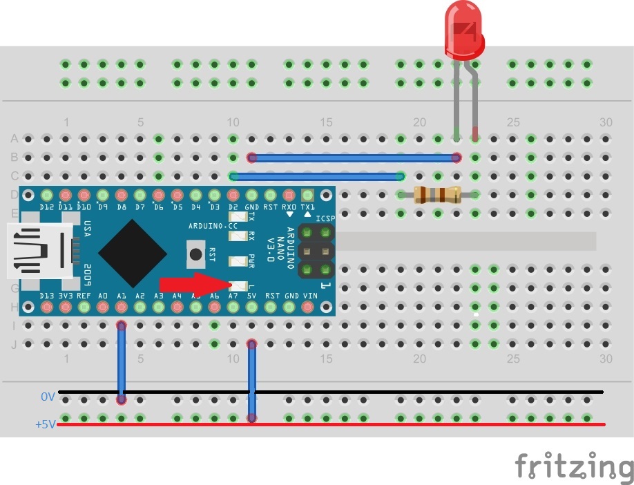
The basic blink sketch is the easiest project to build but don't under estimate it. This sketch can be extremally useful to determine if you have a problem with your board. On the image above is highlighted the BUILTIN_LED for this board, it is connected to GPIO13 and you can use either the GPIO number or the BUILTIN_LED defined name to access it.
Code: /***
* Basic control of output pin
* flashes either the on-board LED or a
*second LED connected to GPIO D2
***/

void setup()
{
  pinMode(BUILT_IN, OUTPUT);
  pinMode(2, OUTPUT);
}

void loop()
{
  digitalWrite(BUILTIN_LED, HIGH);
  digitalWrite(13, LOW);
  delay(1000);
  digitalWrite(BUILTIN_LED, LOW);
  digitalWrite(13, HIGH);
  delay(1000);
}
Pinout

Description of Code Operation
All code blocks will start with #includes, declarations and assignments. This is then followed by the function setup(), here is where the use of the GPIO pin is defined, it can be INPUT, OUTPUT or set as an interrupt (advanced).Here they are both outputs. following this is the loop function, again not returning anything, the pins are set to their starting values, HIGH or LOW, following which is a delay method, this is measured in micro seconds hence 1000uS = 1 second. The pins are again set to their respective output values and a second delay is called. The code within the loop function is then repeated